A mechanism I grew up around.
My grandfather, Leo James “Jim” Hubbard, was a 1949 graduate of the University of Rhode Island whose engineering career included work at Hughes Aircraft, General Electric, and Xerox. He went on to found Precision Handling Devices, turning his patented designs and material innovations into paper-feed equipment sold around the world. URI documents that career.
I grew up around these tractors. My father’s factory did the injection molding for the plastic parts, and I was there all the time as a kid, including working after school. The mechanism fed perforated printer paper using a continuous belt whose pins fit into the holes along the paper’s edge.
This project began with a search for my grandfather’s original patent. Finding the drawings on Google Patents gave me a reference for recreating a mechanism I already knew well, as a model I could turn around, look inside, and watch in motion.
The starting point was his 1974 patent, Feed mechanism. We used Astra to read the description and work through the geometry, Meshy.ai to make an initial visual study, and Blender to build and refine the moving assembly.
Start with the source.
Figure 2 shows a single tractor with its guide plate open. The sectional drawings explain what that view hides: the belt supports, the sprocket recesses, and the shape of each molded drive element.
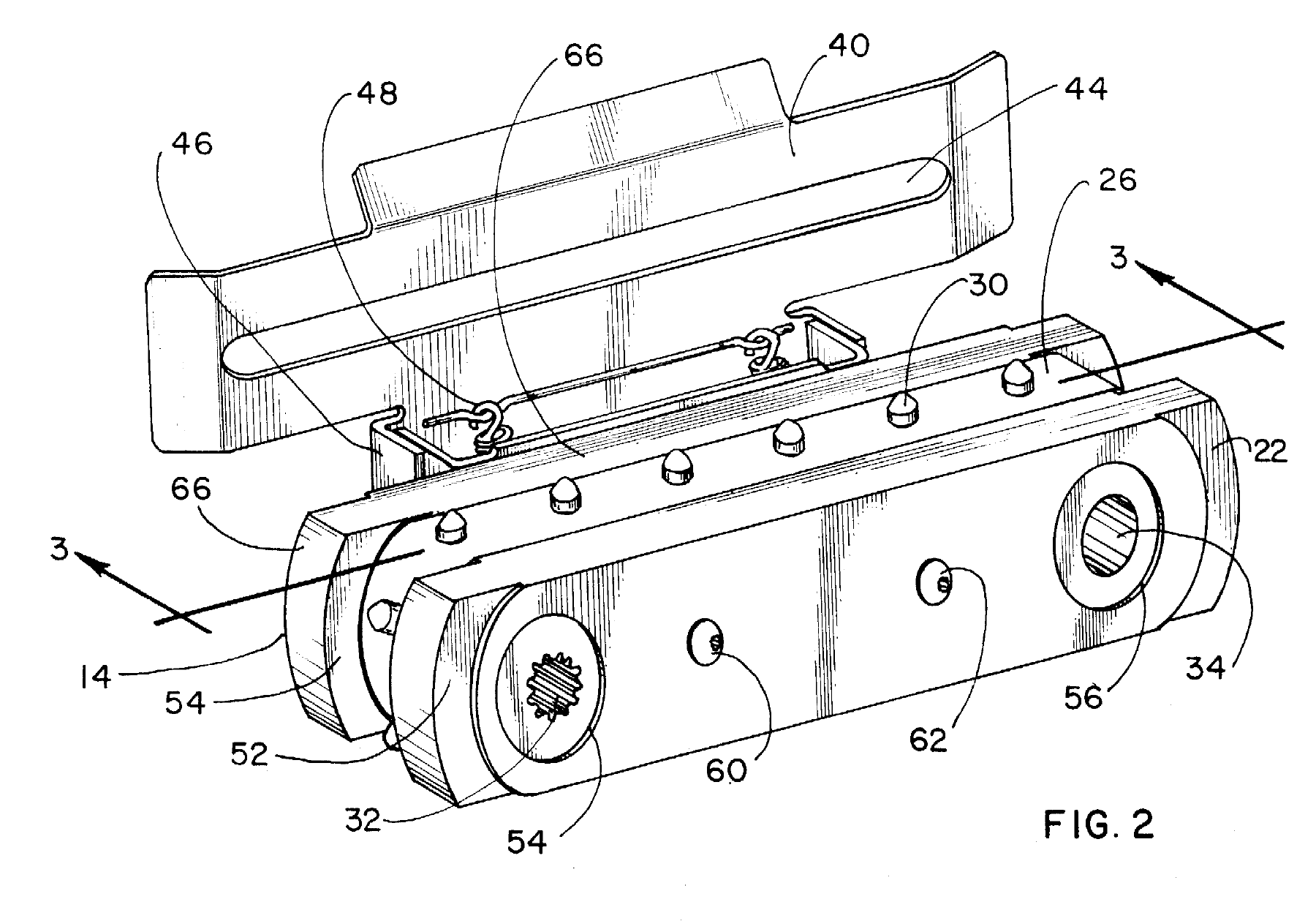
Leo J. Hubbard · July 23, 1974 · Figure 2
Original drawing, cropped and rotated for reading. Part numbers and linework are preserved. The full patent contains 12 figures.
One belt. Two working surfaces.
Above the belt, a pin enters a hole in the paper. Below it, a half-cylinder fits into a rounded recess in the sprocket. Those two portions form one drive element. As the sprocket turns, it carries the belt along a straight feeding path and around each end of the frame.
The slotted guide plate holds the paper close to the belt while giving the pins room to pass. In use, two tractors support the opposite edges of a sheet. This reconstruction concentrates on one tractor, so the engagement is easier to see.
The material mattered.
My recollection is that my grandfather encountered the film through work on electrical components for rockets, before it was widely available, and recognized its potential for a paper-feed belt. Seeing a useful connection between those two applications is part of what makes this mechanism interesting to me.
The patent explicitly names Kapton, DuPont’s polyimide film, among the materials suitable for the belt. The design called for a lightweight strip that could bend repeatedly while maintaining its dimensions and pin spacing. Heat resistance also allowed the drive elements to be molded directly onto the belt. Those properties helped the belt keep the pins aligned with the paper as it moved.
Three tools, distinct roles.
I had never worked with Blender or Meshy before this project. With Astra helping me through the setup, I could get an initial model on screen and then refine it through specific feedback. I could describe what I wanted in ordinary language, then respond to what appeared on screen.
That first result gave us something concrete to work with. Refining the shapes, materials, and motion took further iterations. I could contribute by comparing the model with the drawing and drawing on my experience with the parts in the factory.
Astra Research & construction
Read the patent, connected its different views, and wrote the scripts that built and controlled the Blender model through a local MCP connection.
Meshy.ai A first visual study
Generated a 3D interpretation from Figure 2. The Smart Topology run used five credits and produced a useful silhouette, but several pins and openings were distorted.
Blender Geometry, materials & motion
Held the editable assembly: individually named parts, controlled pin spacing, a hinged guide plate, and synchronized belt and sprocket motion. The website’s viewer uses geometry exported from that file.
The Meshy study stayed alongside the reconstruction for comparison. The moving parts were built separately in Blender, where their spacing and motion could be checked.
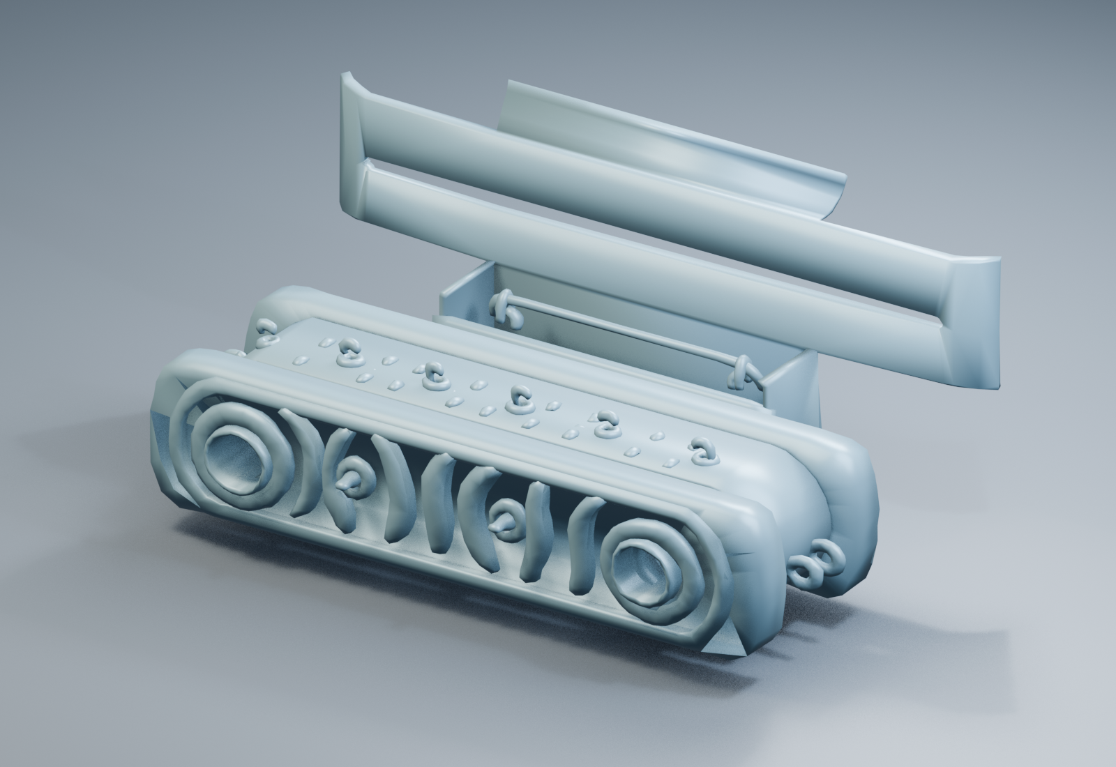 Meshy · first interpretation
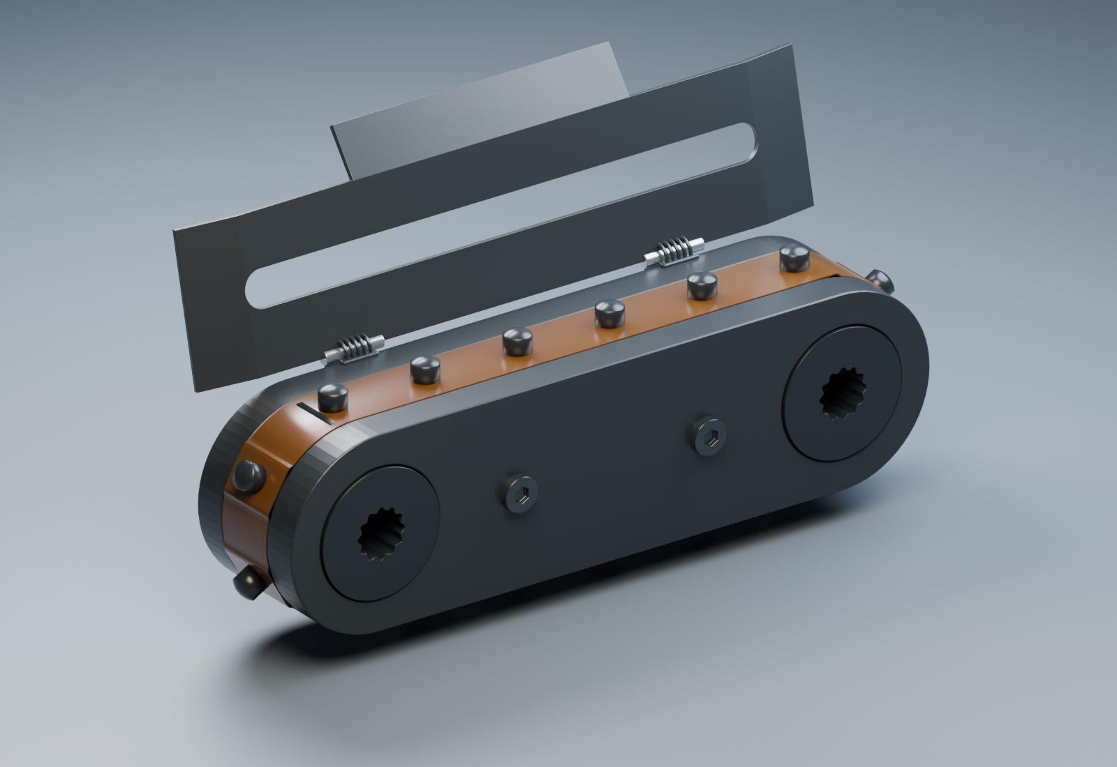 Blender · refined reconstruction
The details that mattered.
The first version had a silver finish. The parts I knew from the factory were black injection-molded plastic. The belt was amber, but it needed to let light through. And the top guide had rounded ends that did not match the patent’s more angular outline.
Those became concrete revisions: black plastic parts, a translucent amber belt, and a guide plate with straight ends, bent sections, and an integrated stepped tab. Comparing the model with the drawing made each correction easier to explain.
The most satisfying part was seeing the pins come around the sprocket and line up with the paper. A mechanism I had grown up around was now moving on screen, built from my grandfather’s patent drawings.
Try it yourself: reference, tools and first model
Here is a small version of the workflow to try with a drawing, a photograph, or an object you know well.
Connect the tools.
My setup used Astra in Codex, Blender running locally with an MCP server, and a Meshy plugin connected to my account. MCP—Model Context Protocol—is the connection that lets the assistant use tools in another application. Ask Astra to walk you through your chosen Blender integration’s setup, then confirm it can read the open scene. Connect Meshy and check that its generation tools are available. The official MCP setup guide explains the Codex side; the Blender integration supplies its own installation steps.
Give it a useful starting image.
Provide the source link or file and say which object matters. We used a cropped, upright version of Figure 2 for Meshy and kept the other patent views available to explain hidden parts. Ask Astra to list visible components and identify any dimensions it would need to estimate.
Make one first draft.
Ask for a simple, untextured Meshy study and a GLB export for Blender. Confirm the credit cost before generation; our particular run used five credits. Inspect the result from several angles. For this mechanism, that revealed why we needed separately constructed moving parts.
Describe specific corrections.
“The frame is black plastic.” “The amber belt should let light through.” “The top guide’s outline needs to match Figure 2.” Feedback like this gave Astra clear changes to make in Blender. Ask it to keep components separately named and save an editable
.blendfile as you go.Add one movement, then check it.
Start with a hinge opening or a wheel turning. For our belt, the next step was matching the pin spacing, sprocket rotation, and paper travel. Ask for a slow preview so you can spot slipping, collisions, or parts moving out of alignment.
You can begin with a subject you understand and let the first draft show you what needs attention. In this project, my knowledge of the object gave me useful feedback to offer from the start.
What the model can tell us.
This is a visual reconstruction, with prescribed motion. The patent establishes the arrangement and operating principle, but it does not supply every dimension needed for an exact replica. Pin pitch, clearances, film thickness, and several small details were estimated. This model has not been validated for manufacture or 3D printing.
The Blender checks confirmed the implemented pin motion and paper alignment. They do not establish the unknown historical measurements. The interactive view shows the same mechanism with a simplified lighting setup for the browser.
The tractor is shown on its own, with open shaft holes. Figure 1 shows separate printer drive and guide shafts passing through the tractors; the short metal stubs in an earlier version of this model have been removed. I also remember slightly more pointed pins, possibly in white plastic. Their color remains uncertain, and the current model retains the rounded cap described in the 1974 patent.
Material sources & family history
The patent identifies Kapton as a belt-material option and discusses its mechanical properties. It does not identify the grade used in the parts I remember or document when my grandfather first obtained the film. The account of early access through work on rocket electrical components comes from family recollection; the specific employer or contract for that work has not been established.
The manufacturer’s history dates Kapton’s introduction to 1965 and identifies aerospace and wire insulation among its initial applications. That provides context, rather than independent confirmation of his access to it.
- Google Patents record US3825162A ↗
- Original patent PDF · 13 pages ↗
- Reconstructed model GLB · 3D geometry ↓
- Model notes Sources & assumptions ↓
The GLB contains geometry and belt shape keys. The animation in this page is driven by the viewer; the downloadable GLB does not contain a baked animation clip.